The OSI Reference Model

In this sample chapter from CompTIA Network+ N10-007 Cert Guide, explore the seven layers of the Open Systems Interconnection (OSI) reference model.
This chapter is from the book
This chapter is from the book
This chapter is from the book
Way back in 1977, the International Organization for Standardization (ISO) developed a subcommittee to focus on the interoperability of multivendor communications systems. This is fancy language for getting network “thingies” to communicate with each other, even if different companies made those network “thingies.” What sprang from this subcommittee was the Open Systems Interconnection (OSI) reference model (referred to as the OSI model or the OSI stack). With this model, you can talk about any networking technology and categorize that technology as residing at one or more of the seven layers of the model.
This chapter defines those seven layers and offers examples of what you might find at each layer. It also contrasts the OSI model with another model—the TCP/IP stack, also known as the Department of Defense (DoD) model—that focuses on Internet Protocol (IP) communications.
Foundation Topics
The Purpose of Reference Models
Throughout this book, various protocols and devices that play a role in your network (and your networking career) are introduced. To better understand how a technology fits in, it helps to have a common point of reference against which various technologies from different vendors can be compared. Understanding the OSI model is useful in troubleshooting networks.
One of the most common ways of categorizing the function of a network technology is to say at what layer (or layers) of the OSI model that technology runs. Based on how that technology performs a certain function at a certain layer of the OSI model allows you to better decide whether one device is going to be able to communicate with another device, which might or might not be using a similar technology at that layer of the OSI reference model.
For example, when your laptop connects to a web server on the Internet, your service provider assigns your laptop an IP address. Similarly, the web server to which you are communicating has an IP address. As you see in this chapter, an IP address lives at Layer 3 (the network layer) of the OSI model. Because both your laptop and the web server use a common protocol (that is, IP) at Layer 3, they are capable of communicating with one another.
Personally, I have been in the computer-networking industry since 1989, and I have had the OSI model explained in many classes I have attended and books I have read. From this, I have taken away a collection of metaphors to help describe the operation of the different layers of the OSI model. Some of the metaphors involve sending a letter from one location to another or placing a message in a series of envelopes. However, my favorite (and a more correct) way to describe the OSI model is to simply think of it as being analogous to a bookshelf, such as the one shown in Figure 2-1.
)
Figure 2-1 A Bookshelf Is Analogous to the OSI Model
If you were to look at a bookshelf in my home, you would see that I organized diverse types of books on different shelves. One shelf has my collection of Star Wars books, another shelf holds the books I wrote for Pearson, another shelf holds my old-school audio books, and so on. I grouped similar books together on a shelf, just as the OSI model groups similar protocols and functions together in a layer.
A common pitfall my readers meet when studying the OSI model is to try to neatly fit all the devices and protocols in their network into one of the OSI model’s seven layers. However, not every technology is a perfect fit into these layers. In fact, some networks might not have any technologies running at one or more of these layers. This reminds me of my favorite statement about the OSI model. It comes from Rich Seifert’s book The Switch Book. In that book, Rich reminds us that the OSI model is a reference model, not a reverence model. That is, no cosmic law states that all technologies must cleanly plug into the model. So, as you discover the characteristics of the OSI model layers throughout this chapter, remember that these layers are like shelves for organizing similar protocols and functions, not immutable laws.
The OSI Model

As previously described, the OSI model consists of seven layers:
Layer 1: The physical layer
Layer 2: The data link layer
Layer 3: The network layer
Layer 4: The transport layer
Layer 5: The session layer
Layer 6: The presentation layer
Layer 7: The application layer
Graphically, we depict these layers with Layer 1 at the bottom of the stack, as shown in Figure 2-2.
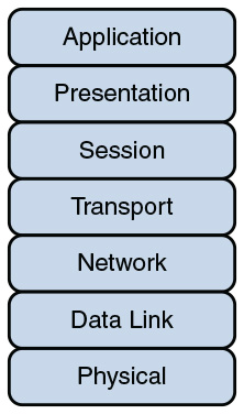
Figure 2-2 OSI “Stack”
Various mnemonics are available to help memorize these layers in their proper order. A top-down (that is, starting at the top of the stack with Layer 7 and working your way down to Layer 1) acrostic is All People Seem To Need Data Processing. As a couple of examples, using this acrostic, the A in All reminds us of the A in Application, and the P in People reminds us of the P in Presentation. Another common memory aid is Please Do Not Throw Sausage Pizza Away, which begins at Layer 1 and works its way up to Layer 7.
At the physical layer, binary expressions (that is, a series of 1s and 0s) represent data. A binary expression is created using bits, where a bit is a single 1 or a single 0. At upper layers, however, bits are grouped together, into what is known as a protocol data unit (PDU) or a data service unit.
Engineers tend to use the term packet generically to refer to these PDUs. However, PDUs might have an added name, depending on their OSI layer. Figure 2-3 illustrates these PDU names. A common memory aid for these PDUs is Some People Fear Birthdays, where the S in Some reminds us of the S in Segments. The P in People reminds us of the P in Packets, and the F in Fear reflects the F in Frames. Finally, the B in Birthdays reminds us of the B in Bits.
)
Figure 2-3 PDU Names
Layer 1: The Physical Layer
The concern of the physical layer, as shown in Figure 2-4, is the transmission of bits on the network along with the physical and electrical characteristics of the network.
)
Figure 2-4 Layer 1: The Physical Layer
The physical layer defines the following:
How to represent bits on the medium: Data on a computer network is represented as a binary expression. Chapter 5, “IPv4 and IPv6 Addresses,” discusses binary in much more detail. Electrical voltage (on copper wiring) or light (carried via fiber-optic cabling) can represent these 1s and 0s.
For example, the presence or the absence of voltage on a wire portrays a binary 1 or a binary 0, respectively, as illustrated in Figure 2-5. Similarly, the presence or absence of light on a fiber-optic cable renders a 1 or 0 in binary. This type of approach is called current state modulation.
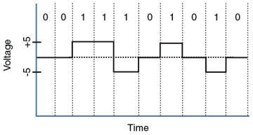
Figure 2-5 Current State Modulation
An alternate approach to portraying binary data is state transition modulation, as shown in Figure 2-6, where the transition between voltages or the presence of light shows a binary value.
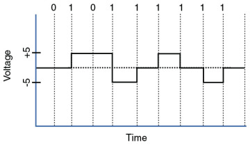
Figure 2-6 Transition Modulation
Wiring standards for connectors and jacks: Chapter 3, “Network Components,” describes several standards for network connectors. For example, the TIA/EIA-568-B standard describes how to wire an RJ-45 connector for use on a 100BASE-TX Ethernet network, as shown in Figure 2-7.
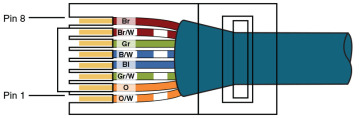
Figure 2-7 TIA/EIA-568-B Wiring Standard for an RJ-45 Connector
Physical topology: Layer 1 devices view a network as a physical topology (as opposed to a logical topology). Examples of a physical topology include bus, ring, and star topologies, as described in Chapter 1, “Computer Network Fundamentals.”
Synchronizing bits: For two networked devices to successfully communicate at the physical layer, they must agree on when one bit stops and another bit starts. Specifically, the devices need a method to synchronize the bits. Two basic approaches to bit synchronization include asynchronous and synchronous synchronization:
Asynchronous: With this approach, a sender states that it is about to start transmitting by sending a start bit to the receiver. When the receiver sees this, it starts its own internal clock to measure the next bits. After the sender transmits its data, it sends a stop bit to say that it has finished its transmission.
Synchronous: This approach synchronizes the internal clocks of both the sender and the receiver to ensure that they agree on when bits begin and end. A common approach to make this synchronization happen is to use an external clock (for example, a clock given by a service provider). The sender and receiver then reference this external clock.
Bandwidth usage: The two fundamental approaches to bandwidth usage on a network are broadband and baseband:
Broadband: Broadband technologies divide the bandwidth available on a medium (for example, copper or fiber-optic cabling) into different channels. A sender can then transmit different communication streams over the various channels. For example, consider frequency-division multiplexing (FDM) used by a cable modem. Specifically, a cable modem uses certain ranges of frequencies on the cable coming into your home from the local cable company to carry incoming data, another range of frequencies for outgoing data, and several other frequency ranges for various TV stations.
Baseband: Baseband technologies, in contrast, use all the available frequencies on a medium to send data. Ethernet is an example of a networking technology that uses baseband.
Multiplexing strategy: Multiplexing allows multiple communications sessions to share the same physical medium. Cable TV, as previously mentioned, allows you to receive multiple channels over a single physical medium (for example, a coaxial cable plugged into the back of your television). Here are some of the more common approaches to multiplexing:
Time-division multiplexing (TDM): TDM supports different communication sessions (for example, different telephone conversations in a telephony network) on the same physical medium by causing the sessions to take turns. For a brief period, defined as a time slot, data from the first session is sent, followed by data from the second session. This continues until all sessions have had a turn, and the process repeats itself.
Statistical time-division multiplexing (StatTDM): A downside to TDM is that each communication session receives its own time slot, even if one of the sessions does not have any data to send at the moment. To make a more efficient use of available bandwidth, StatTDM dynamically assigns time slots to communications sessions on an as-needed basis.
Frequency-division multiplexing (FDM): FDM divides a medium’s frequency range into channels, and different communication sessions send their data over different channels. As previously described, this approach to bandwidth usage is called broadband.
)
)
)
Examples of devices defined by physical layer standards include hubs, wireless access points, and network cabling.
Layer 2: The Data Link Layer
The data link layer is concerned with the following:
Packaging data into frames and transmitting those frames on the network
Performing error detection/correction
Uniquely finding network devices with an address
Handling flow control
These processes are referred to collectively as data link control (DLC) and are illustrated in Figure 2-8.
)
Figure 2-8 Layer 2: The Data Link Layer
In fact, the data link layer is unique from the other layers in that it has two sublayers of its own: MAC and LLC.
Media Access Control
Characteristics of the Media Access Control (MAC) sublayer include the following:
Physical addressing: A common example of a Layer 2 address is a MAC address, which is a 48-bit address assigned to a device’s network interface card (NIC). MAC addresses are written in hexadecimal notation (for example, 58:55:ca:eb:27:83). The first 24 bits of the 48-bit address is the vendor code. The IEEE Registration Authority assigns a manufacturer one or more unique vendor codes. You can use the list of vendor codes at http://standards.ieee.org/develop/regauth/oui/oui.txt to identify the manufacturer of a networking device, based on the first half of the device’s MAC address. The last 24 bits of a MAC address are assigned by the manufacturer, and they act as a serial number for the device. No two MAC addresses in the world should have the same value.
Logical topology: Layer 2 devices view a network as a logical topology. Examples of a logical topology include bus and ring topologies, as described in Chapter 1.
Method of transmitting on the media: With several devices connected to a network, there needs to be some strategy for deciding when a device sends on the media. Otherwise, multiple devices might send at the same time and thus interfere with one another’s transmissions.
Logical Link Control
Characteristics of the Logical Link Control (LLC) sublayer include the following:
Connection services: When a device on a network receives a message from another device on the network, that recipient device can give feedback to the sender in the form of an acknowledgment message. The two main functions provided by these acknowledgment messages are as follows:
Flow control: Limits the amount of data a sender can send at one time; this prevents the sender from overwhelming the receiver with too much information.
Error control: Allows the recipient of data to let the sender know whether the expected data frame was not received or whether it was received but is corrupted. The recipient figures out whether the data frame is corrupt by mathematically calculating a checksum of the data received. If the calculated checksum does not match the checksum received with the data frame, the recipient of the data draws the conclusion that the data frame is corrupted and can then notify the sender via an acknowledgment message.
Synchronizing transmissions: Senders and receivers of data frames need to coordinate when a data frame is being transmitted and should be received. The three methods of performing this synchronization are detailed here:
Isochronous: With isochronous transmission, network devices look to a common device in the network as a clock source, which creates fixed-length time slots. Network devices can determine how much free space, if any, is available within a time slot and then insert data into an available time slot. A time slot can accommodate more than one data frame. Isochronous transmission does not need to provide clocking at the beginning of a data string (as does synchronous transmission) or for every data frame (as does asynchronous transmission). As a result, isochronous transmission uses little overhead when compared to asynchronous or synchronous transmission methods.
Asynchronous: With asynchronous transmission, network devices reference their own internal clocks, and network devices do not need to synchronize their clocks. Instead, the sender places a start bit at the beginning of each data frame and a stop bit at the end of each data frame. These start and stop bits tell the receiver when to monitor the medium for the presence of bits.
An additional bit, called the parity bit, might also be added to the end of each byte in a frame to detect an error in the frame. For example, if even parity error detection (as opposed to odd parity error detection) is used, the parity bit (with a value of either 0 or 1) would be added to the end of a byte, causing the total number of 1s in the data frame to be an even number. If the receiver of a byte is configured for even parity error detection and receives a byte where the total number of bits (including the parity bit) is even, the receiver can conclude that the byte was not corrupted during transmission.
Synchronous: With synchronous transmission, two network devices that want to communicate between themselves must agree on a clocking method to show the beginning and ending of data frames. One approach to providing this clocking is to use a separate communications channel over which a clock signal is sent. Another approach relies on specific bit combinations or control characters to indicate the beginning of a frame or a byte of data.
Like asynchronous transmissions, synchronous transmissions can perform error detection. However, rather than using parity bits, synchronous communication runs a mathematical algorithm on the data to create a cyclic redundancy check (CRC). If both the sender and the receiver calculate the same CRC value for the same chunk of data, the receiver can conclude that the data was not corrupted during transmission.
Examples of devices defined by data link layer standards include switches, bridges, and NICs.
Layer 3: The Network Layer
The network layer, as shown in Figure 2-9, is primarily concerned with forwarding data based on logical addresses.
)
Figure 2-9 Layer 3: The Network Layer
Although many network administrators think of routing and IP addressing when they hear about the network layer, this layer is actually responsible for a variety of tasks:
Logical addressing: Whereas the data link layer uses physical addresses to make forwarding decisions, the network layer uses logical addressing to make forwarding decisions. A variety of routed protocols (for example, AppleTalk and IPX) have their own logical addressing schemes, but by far, the most widely deployed routed protocol is Internet Protocol (IP). Chapter 5 discusses IP addressing in detail.
Switching: Engineers often associate the term switching with Layer 2 technologies; however, the concept of switching also exists at Layer 3. Switching, at its essence, is making decisions about how data should be forwarded. At Layer 3, three common switching techniques exist:
Packet switching: With packet switching, a data stream is divided into packets. Each packet has a Layer 3 header that includes a source and destination Layer 3 address. Another term for packet switching is routing, which is discussed in more detail in Chapter 6, “Routing IP Packets.”
Circuit switching: Circuit switching dynamically brings up a dedicated communication link between two parties for those parties to communicate.
As a simple example of circuit switching, think of making a phone call from your home to a business. Assuming you have a traditional landline servicing your phone, the telephone company’s switching equipment interconnects your home phone with the phone system of the business you are calling. This interconnection (that is, circuit) only exists for the duration of the phone call.
Message switching: Unlike packet switching and circuit switching technologies, message switching is usually not well suited for real-time applications because of the delay involved. Specifically, with message switching, a data stream is divided into messages. Each message is tagged with a destination address, and the messages travel from one network device to another network device on the way to their destination. Because these devices might briefly store the messages before forwarding them, a network using message switching is sometimes called a store-and-forward network. Metaphorically, you could visualize message switching like routing an email message, where the email message might be briefly stored on an email server before being forwarded to the recipient.
Route discovery and selection: Because Layer 3 devices make forwarding decisions based on logical network addresses, a Layer 3 device might need to know how to reach various network addresses. For example, a common Layer 3 device is a router. A router can maintain a routing table indicating how to forward a packet based on the packet’s destination network address.
A router can have its routing table populated via manual configuration (that is, by entering static routes), via a dynamic routing protocol (for example, RIP, OSPF, or EIGRP), or simply by the fact that the router is directly connected to certain networks.
Connection services: Just as the data link layer offers connection services for flow control and error control, connection services also exist at the network layer. Connection services at the network layer can improve the communication reliability, if the data link’s LLC sublayer is not performing connection services.
The following functions are performed by connection services at the network layer:
Flow control (also known as congestion control): Helps prevent a sender from sending data more rapidly than the receiver is capable of receiving it.
Packet reordering: Allows packets to be placed in the proper sequence as they are sent to the receiver. This might be necessary because some networks support load balancing, where multiple links are used to send packets between two devices. Because multiple links exist, packets might arrive out of order.
Examples of devices found at the network layer include routers and multilayer switches. The most common Layer 3 protocol in use, and the protocol on which the Internet is based, is IPv4. However, IPv6 is beginning to be more common on networks today.
Layer 4: The Transport Layer
The transport layer, as shown in Figure 2-10, acts as a dividing line between the upper layers and lower layers of the OSI model. Specifically, messages are taken from upper layers (Layers 5–7) and are encapsulated into segments for transmission to the lower layers (Layers 1–3). Similarly, data streams coming from lower layers are de-encapsulated and sent to Layer 5 (the session layer), or some other upper layer, depending on the protocol.
)
Figure 2-10 Layer 4: The Transport Layer
Two common transport layer protocols are Transmission Control Protocol (TCP) and User Datagram Protocol (UDP):
Transmission Control Protocol (TCP): A connection-oriented transport protocol. Connection-oriented transport protocols offer reliable transport, in that if a segment is dropped, the sender can detect that drop and retransmit the dropped segment. Specifically, a receiver acknowledges segments that it receives. Based on those acknowledgments, a sender can decide which segments were successfully received and which segments need to be transmitted again.
User Datagram Protocol (UDP): A connectionless transport protocol. Connectionless transport protocols offer unreliable transport, in that if a segment is dropped, the sender is unaware of the drop, and no retransmission occurs.
Just as Layer 2 and Layer 3 offer flow control services, flow control services also exist at Layer 4. Two common flow control approaches at Layer 4 are windowing and buffering:
Windowing: TCP communication uses windowing, in that one or more segments are sent at one time, and a receiver can attest to the receipt of all the segments in a window with a single acknowledgment. In some cases, as illustrated in Figure 2-11, TCP uses a sliding window, where the window size begins with one segment. If there is a successful acknowledgment of that one segment (that is, the receiver sends an acknowledgment asking for the next segment), the window size doubles to two segments. Upon successful receipt of those two segments, the next window holds four segments. This exponential increase in window size continues until the receiver does not acknowledge successful receipt of all segments within a certain amount of time—known as the round-trip time (RTT), which is sometimes called real transfer time—or until a configured maximum window size is reached.
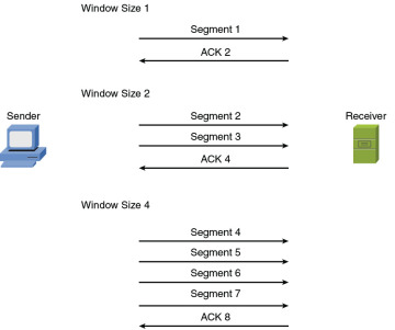
Figure 2-11 TCP Sliding Window
Buffering: With buffering, a device (for example, a router) uses a chunk of memory (sometimes called a buffer or a queue) to store segments if bandwidth is not available to send those segments. A queue has a finite capacity, however, and can overflow (that is, drop segments) in case of sustained network congestion.
)
In addition to TCP and UDP, Internet Control Message Protocol (ICMP) is another transport layer protocol you are likely to meet. ICMP is used by utilities such as ping and traceroute, which are discussed in Chapter 10, “Command-Line Tools.”
Layer 5: The Session Layer
The session layer, as shown in Figure 2-12, is responsible for setting up, maintaining, and tearing down sessions. You can think of a session as a conversation that needs to be treated separately from other sessions to avoid the intermingling of data from different conversations.
)
Figure 2-12 Layer 5: The Session Layer
Here is a detailed look at the functions of the session layer:
Setting up a session: Examples of the procedures involved in setting up a session include the following:
Checking user credentials (for example, username and password)
Assigning numbers to a session’s communication flows to uniquely find each one
Negotiating services needed during the session
Negotiating which device begins sending data
Maintaining a session: Examples of the procedures involved in supporting a session include the following:
Transferring data
Reestablishing a disconnected session
Acknowledging receipt of data
Tearing down a session: A session can be disconnected based on agreement of the devices in the session. Alternatively, a session might be torn down because one party disconnects (either intentionally or because of an error condition). If one party disconnects, the other party can detect a loss of communication with that party and tear down its side of the session.
H.323 is an example of a session layer protocol, which can help set up, support, and tear down a voice or video connection. Keep in mind, however, that not every network application neatly maps directly to all seven layers of the OSI model. The session layer is one of those layers where it might not be possible to name what protocol in each scenario is running in it. Network Basic Input/Output System (NetBIOS) is one example of a session layer protocol.
Layer 6: The Presentation Layer
The presentation layer, as shown in Figure 2-13, handles formatting the data being exchanged and securing that data with encryption.
)
Figure 2-13 Layer 6: The Presentation Layer
The following list describes the function of data formatting and encryption in more detail:
Data formatting: As an example of how the presentation layer handles data formatting, consider how text is formatted. Some applications might format text using American Standard Code for Information Interchange (ASCII), while other applications might format text using Extended Binary Coded Decimal Interchange Code (EBCDIC). The presentation layer handles formatting the text (or other types of data, such as multimedia or graphics files) in a format that allows compatibility between the communicating devices.
Encryption: Imagine that you are sending sensitive information over a network (for example, your credit card number or bank password). If a malicious user were to intercept your transmission, they might be able to obtain this sensitive information. To add a layer of security for such transmissions, encryption can be used to scramble up (encrypt) the data in such a way that if the data were intercepted, a third party would not be able to unscramble it (decrypt). However, the intended recipient would be able to decrypt the transmission.
Encryption is discussed in detail in Chapter 12, “Network Security.”
Layer 7: The Application Layer
The application layer, as shown in Figure 2-14, gives application services to a network. An important (and often-misunderstood) concept is that end-user applications (such as Microsoft Word) live at the application layer. Instead, the application layer supports services used by end-user applications. For example, email is an application layer service that does exist at the application layer, whereas Microsoft Outlook (an example of an email client) is an end-user application that does not live at the application layer. Another function of the application layer is advertising available services.
)
Figure 2-14 Layer 7: The Application Layer
The following describes the functions of the application layer in more detail:
Application services: Examples of the application services living at the application layer include file sharing and email.
Service advertisement: Some applications’ services (for example, some networked printers) periodically send out advertisements, making their availability known to other devices on the network. Other services, however, register themselves and their services with a centralized directory (for example, Microsoft Active Directory), which can be queried by other network devices seeking such services.
Recall that even though the application layer is numbered as Layer 7, it is at the top of the OSI stack because its networking functions are closest to the end user.
The TCP/IP Stack
The ISO developed the OSI reference model to be generic, in terms of what protocols and technologies could be categorized by the model. However, most of the traffic on the Internet (and traffic on corporate networks) is based on the TCP/IP protocol suite. Therefore, a more relevant model for many network designers and administrators to reference is a model developed by the United States Department of Defense (DoD). This model is known as the DoD model or the TCP/IP stack.
Layers of the TCP/IP Stack
The TCP/IP stack has only four defined layers, as opposed to the seven layers of the OSI model. Figure 2-15 contrasts these two models for an illustrative understanding.
)
Figure 2-15 TCP/IP Stack
The TCP/IP stack is composed of the following layers:
Network interface: The TCP/IP stack’s network interface layer encompasses the technologies offered by Layers 1 and 2 (the physical and data link layers) of the OSI model.
Internet: The Internet layer of the TCP/IP stack maps to Layer 3 (the network layer) of the OSI model. Although multiple routed protocols (for example, IP, IPX, and AppleTalk) live at the OSI model’s network layer, the Internet layer of the TCP/IP stack focuses on IP as the protocol to be routed through a network. Figure 2-16 shows the format of an IP Version 4 packet.
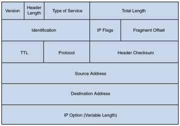
Figure 2-16 IP Version 4 Packet Format
Notice that there are fields in the IP packet header for both a source and a destination IP address. The Protocol field shows the transport layer protocol from which the packet was sent or to which the packet should be sent. Also of note is the Time-to-Live (TTL) field. The value in this field is decremented by 1 every time this packet is routed from one IP network to another (that is, passes through a router). If the TTL value ever reaches 0, the packet is discarded from the network. This behavior helps prevent routing loops. As a common practice, the OSI layer numbers of 1, 2, and 3 are still used when referring to physical, data link, and network layers of the TCP/IP stack, even though the TCP/IP stack does not explicitly separate the physical and data link layers.
Transport: The transport layer of the TCP/IP stack maps to Layer 4 (the transport layer) of the OSI model. The two primary protocols found at the TCP/IP stack’s transport layer are TCP and UDP.
Figure 2-17 details the structure of a TCP segment. Notice the fields for source and destination ports. As described later in this chapter, these ports identify to which upper-layer protocol data should be forwarded, or from which upper-layer protocol the data is being sent.
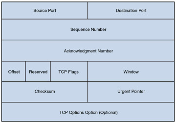
Figure 2-17 TCP Segment Format
Also notice the field for window size. The value in this field determines how many bytes a device can receive before expecting an acknowledgment. As previously described, this feature offers flow control.
The header of a TCP segment also contains sequence numbers for segments. With sequence numbering, if segments arrive out of order, the recipient can put them back in the proper order based on these sequence numbers.
The acknowledgment number in the header shows the next sequence number the receiver expects to receive. This is a way for the receiver to let the sender know that all segments up to and including that point have been received. Due to the sequencing and acknowledgements, TCP is considered to be a connection-oriented transport layer protocol.
Figure 2-18 presents the structure of a UDP segment. UDP is a connectionless, unreliable protocol. UDP lacks the sequence numbering, window size, and acknowledgment numbering present in the header of a TCP segment. The UDP segment’s header simply contains source and destination port numbers, a UDP checksum (which is an optional field used to detect transmission errors), and the segment length (measured in bytes).
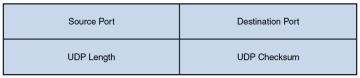
Figure 2-18 UDP Segment Format
Because a UDP header is so much smaller than a TCP header, UDP becomes a good candidate for the transport layer protocol for applications that need to maximize bandwidth and do not require acknowledgments (for example, audio or video streams).
Application: The biggest difference between the TCP/IP stack and the OSI model is found at the TCP/IP stack’s application layer. This layer addresses concepts described by Layers 5, 6, and 7 (the session, presentation, and application layers) of the OSI model.
)
)
)
)
With the reduced complexity of a four-layer model like the TCP/IP stack, network designers and administrators can more easily categorize a given networking technology into a specific layer. For example, although H.323 was shown earlier as a session layer protocol within the OSI model, you would have to know more about the behavior of H.323 to properly categorize it. However, with the TCP/IP stack, you could quickly figure out that H.323 is a higher-level protocol that gets encapsulated inside of TCP, and thus classify H.323 in the application layer of the TCP/IP stack.
Common Application Protocols in the TCP/IP Stack
Application layer protocols in the TCP/IP stack are identifiable by unique port numbers. For example, when you enter a web address in an Internet browser, you are (by default) communicating with that remote web address using TCP port 80. Specifically, Hypertext Transfer Protocol (HTTP), which is the protocol used by web servers, uses TCP port 80. Therefore, the data you send to that remote web server has a destination port number of 80. That data is then encapsulated into a TCP segment at the transport layer. That segment is then further encapsulated into a packet at the Internet layer and sent out on the network using an underlying network interface layer technology such as Ethernet.
Continuing with the example depicted in Figure 2-19, when you send traffic to that remote website, the packet you send out to the network needs not only the destination IP address (172.16.1.2 in this example) of the web server and the destination port number for HTTP (that is, 80), it also needs the source IP address of your computer (10.1.1.1 in this example). Because your computer is not acting as a web server, its port is not 80. Instead, your computer selects a source port number greater than 1023. In this example, let’s imagine that the client PC selects the source port 1248.
)
Figure 2-19 Example: Port Numbers and IP Addresses
Notice that when the web server sends content back, the IP addresses and port numbers have now switched, with the web server as the source and your PC as the destination. With both source and destination port numbers, along with source and destination IP addresses, two-way communication becomes possible.
Table 2-1 serves as a reference for some of the more popular application layer protocols and applications found in the TCP/IP stack. Some protocols or applications (such as DNS) may use TCP or UDP for their transport protocol, depending on the specific function being performed.
Table 2-1 Application Layer Protocols/Applications
| Protocol | Description | TCP Port | UDP Port |
| DHCP | Dynamic Host Configuration Protocol: Dynamically assigns IP address information (for example, IP address, subnet mask, DNS server’s IP address, and default gateway’s IP address) to a network device | 67, 68 | |
| DNS | Domain Name System: Resolves domain names to corresponding IP addresses | 53 | 53 |
| FTP | File Transfer Protocol: Transfers files with a remote host (typically requires authentication of user credentials) | 20 and 21 | |
| H.323 | A signaling protocol that provides multimedia communications over a network | 1720 | |
| HTTP | Hypertext Transfer Protocol: Retrieves content from a web server | 80 | |
| HTTPS | Hypertext Transfer Protocol Secure: Used to securely retrieve content from a web server | 443 | |
| IMAP | Internet Message Access Protocol: Retrieves email from an email server | 143 | |
| IMAP4 | Internet Message Access Protocol Version 4: Retrieves email from an email server | 143 | |
| LDAP | Lightweight Directory Access Protocol: Provides directory services (for example, a user directory that includes username, password, email, and phone number information) to network clients | 389 | |
| LDAPS | Lightweight Directory Access Protocol over SSH: A secured version of LDAP | 636 | |
| MGCP | Media Gateway Control Protocol: Used as a call control and communication protocol for Voice over IP networks | 2427, 2727 | |
| NetBIOS | Network Basic Input/Output System: Provides network communication services for LANs that use NetBIOS | 139 | 137, 138 |
| NNTP | Network News Transport Protocol: Supports the posting and reading of articles on Usenet news servers | 119 | |
| NTP | Network Time Protocol: Used by a network device to synchronize its clock with a time server (NTP server) | 123 | |
| POP3 | Post Office Protocol Version 3: Retrieves email from an email server | 110 | |
| RDP | Remote Desktop Protocol: A Microsoft protocol that allows a user to view and control the desktop of a remote computer | 3389 | |
| rsh | Remote Shell: Allows commands to be executed on a computer from a remote user | 514 | |
| RTP | Real-time Transport Protocol: Used for delivering media-based data (such as Voice over IP) through the network | 5004, 5005 | 5004, 5005 |
| RTSP | Real-Time Streaming Protocol: Communicates with a media server (for example, a video server) and controls the playback of the server’s media files | 554 | 554 |
| SCP | Secure Copy: Provides a secure file-transfer service over an SSH connection and offers a file’s original date and time information, which is not available with FTP | 22 | |
| SFTP | Secure FTP: Provides FTP file-transfer service over an SSH connection | 22 | |
| SIP | Session Initiation Protocol: Used to create and end sessions for one or more media connections, including Voice over IP calls | 5061 | 5060 |
| SMB | Server Message Block: Used to share files, printers, and other network resources | 445 | |
| SMTP | Simple Mail Transfer Protocol: Used for sending email | 25 | |
| SNMP | Simple Network Management Protocol: Used to monitor and manage network devices | 161 | |
| SNMP Trap | Simple Network Management Protocol Trap: A notification sent from an SNMP agent to an SNMP manager | 162 | 162 |
| SNTP | Simple Network Time Protocol: Supports time synchronization among network devices, similar to Network Time Protocol (NTP), although SNTP uses a less complex algorithm in its calculation and is slightly less accurate than NTP | 123 | |
| SSH | Secure Shell: Used to securely connect to a remote host (typically via a terminal emulator) | 22 | |
| Telnet | Telnet: Used to connect to a remote host (typically via a terminal emulator) | 23 | |
| TFTP | Trivial File Transfer Protocol: Transfers files with a remote host (does not require authentication of user credentials) | 69 |
Real-World Case Study
Bob, a manager of the networking team at Acme, Inc., is paying extra attention to the specific words he uses as he talks to his team in preparation for the implementation of the network. When referring to transport protocols such as the connection-oriented TCP and the connectionless UDP, the word Bob uses to describe those protocol data units is segment.
In discussing the applications that the company will be using over its network, Bob notes that many of these applications will be using TCP at the transport layer. This includes HTTP for web browsing, HTTPS for secure web traffic, and SMTP and IMAP for email services.
The SSH protocol, which also uses TCP at the transport layer, is a secure method that the company will use to remotely connect to and manage its network devices. A common connectionless UDP protocol is DNS, which will be used thousands of times a day to translate a friendly name like http://www.pearson.com to an IP address that is reachable over the network. Another protocol based on UDP that will be used often is Dynamic Control Host Protocol (DHCP), which assigns client computers on the network an IP address that is required for sending and receiving Layer 3 packets.
For the traffic on the LAN, the Ethernet cables and electronic signals being sent as bits going over those cables represent Layer 1 from an OSI perspective. On the LAN, they will be using Ethernet technology, and as a result the Layer 2 frames that are sent on the LAN will be encapsulated and sent as Ethernet Layer 2 frames.
For datagrams being sent across the serial WAN connections provided by the service provider, it is likely that either PPP or HDLC encapsulation will be used for the Layer 2 frames. On both the LAN and the WAN, at Layer 3 (the network layer), IPv4 will be used for host addressing and defining networks. The same Layer 1, Layer 2, and Layer 3 infrastructure is also capable of transporting IPv6, if desired.
Inside the Layer 3 IP headers, each packet contains the source and destination address, in addition to the information to tell the receiving network device about which Layer 4 transport protocol is encapsulated or carried inside of the Layer 3 packet. When a network device receives the packet and opens it up to look at the contents, this process is called de-encapsulation. As the recipient de-encapsulates and looks at the Layer 4 information, it identifies the application layer protocol or service being used. A segment going to a web server is likely to have a TCP destination port of 80 or 443, depending on whether encryption is being used for a secure connection. A DNS request uses a UDP destination port of 53.
Summary
Here are the main topics covered in this chapter:
The ISO’s OSI reference model consists of seven layers: physical (Layer 1), data link (Layer 2), network (Layer 3), transport (Layer 4), session (Layer 5), presentation (Layer 6), and application (Layer 7). The purpose of each layer was presented, along with examples of technologies living at the individual layers, as it pertains to networking.
The TCP/IP stack was presented as an alternative model to the OSI reference model. The TCP/IP stack consists of four layers: network interface, Internet, transport, and application. These layers were compared with the seven layers of the OSI model.
This chapter discussed how port numbers are used to associate data at the transport layer with a proper application layer protocol. Examples of common application layer protocols in the TCP/IP suite were presented, along with their port numbers.