- Establishing OSPF Neighbor Relationships
- Building the Link-State Database
- Optimizing OSPF Behavior
- OSPFv3
- Summary
- Review Questions
This chapter is from the book
This chapter is from the book
This chapter is from the book
Optimizing OSPF Behavior
Scalability, improved CPU and memory utilization, and the ability to mix small routers with large routers are all the benefits of using proper route summarization techniques. A key feature of the OSPF protocol is the ability to summarize routes at area and autonomous system boundaries.
Route summarization is important because it reduces the amount of the OSPF LSA flooding and the sizes of LSDBs and routing tables, which also reduces the memory and the CPU utilization on the routers. An OSPF network can scale to very large sizes, partially because of the route summarization.
The OSPF protocol defines several special-case area types, including stub areas, totally stubby areas, and NSSAs. The purpose of all three types of stub areas is to inject default routes into an area so that external and summary LSAs are not flooded. Stub areas are designed to reduce the amount of flooding, the LSDB size, and the routing table size in routers within the area. Network designers should always consider using stub area techniques when building networks. Stub area techniques improve performance in OSPF networks and allow the network to scale to significantly larger sizes.
Default routes reduce the routing table size, and also reduce the memory and the CPU utilization. OSPF injects a default route unconditionally or based on the presence of a default route inside the routing table.
This section defines different types of route summarization and describes the configuration commands for each type. It also describes the OSPF area types and the benefits of default routes.
Upon completing this section, you will be able to do the following:
- Describe the properties of OSPF route summarization
- Describe benefits of route summarization in OSPF
- Configure summarization on ABR
- Configure summarization on ASBR
- Configure the cost of OSPF default route
- Describe how you can use default routes and stub routing to direct traffic toward the Internet
- Describe the NSSA areas
- Configure the default route using the default-information originate command
OSPF Route Summarization
Route summarization is a key to scalability in OSPF. Route summarization helps solve two major problems:
- Large routing tables
- Frequent LSA flooding throughout the autonomous system
Every time that a route disappears in one area, routers in other areas also get involved in shortest-path calculation. To reduce the size of the area database, you can configure summarization on an area boundary or autonomous system boundary.
Normally, type 1 and type 2 LSAs are generated inside each area and translated into type 3 LSAs in other areas. With route summarization, the ABRs or ASBRs consolidate multiple routes into a single advertisement. ABRs summarize type 3 LSAs, and ASBRs summarize type 5 LSAs. Instead of advertising many specific prefixes, advertise only one summary prefix.
If the OSPF design includes many ABRs or ASBRs, suboptimal routing is possible. This is one of the drawbacks of summarization.
Route summarization requires a good addressing plan—an assignment of subnets and addresses that is based on the OSPF area structure and lends itself to aggregation at the OSPF area borders.
Benefits of Route Summarization
Route summarization directly affects the amount of bandwidth, CPU power, and memory resources that the OSPF routing process consumes. Without route summarization, every specific-link LSA is propagated into the OSPF backbone and beyond, causing unnecessary network traffic and router overhead.
With route summarization, only the summarized routes are propagated into the backbone (area 0), as illustrated in Figure 3-24. Summarization prevents every router from having to rerun the SPF algorithm, increases the stability of the network, and reduces unnecessary LSA flooding. Also, if a network link fails, the topology change is not propagated into the backbone (and other areas by way of the backbone). Specific-link LSA flooding outside the area does not occur.
)
Figure 3-24 OSPF Route Summarization
Receiving a type 3 LSA into its area does not cause a router to run the SPF algorithm. The routes being advertised in the type 3 LSAs are appropriately added to or deleted from the router’s routing table, but an SPF calculation is not done.
Configuring OSPF Route Summarization
In this section, we will implement route summarization on the area borders in an OSPF environment, shown in Figure 3-25. We will summarize the OSPF network using different subnet sizes and examine the impact of summarization on the OSPF database and routing.
)
Figure 3-25 OSPF Route Summarization Topology
Example 3-49 displays OSPF routes in R1’s routing table.
Example 3-49 OSPF Routes in R1’s Routing Table
R1# show ip route ospf <Output omitted> O 192.168.2.0/24 [110/11] via 172.16.12.2, 00:41:47, Ethernet0/1 O 192.168.3.0/24 [110/11] via 172.16.13.2, 00:40:01, Ethernet0/2 O 192.168.4.0/24 [110/11] via 172.16.14.2, 00:38:09, Ethernet0/0O 192.168.20.0/24 [110/11] via 172.16.12.2, 00:41:37, Ethernet0/1O 192.168.21.0/24 [110/11] via 172.16.12.2, 01:03:46, Ethernet0/1O 192.168.22.0/24 [110/11] via 172.16.12.2, 01:03:36, Ethernet0/1O 192.168.23.0/24 [110/11] via 172.16.12.2, 01:03:26, Ethernet0/1O 192.168.32.0/24 [110/11] via 172.16.13.2, 00:40:14, Ethernet0/2O 192.168.33.0/24 [110/11] via 172.16.13.2, 00:57:01, Ethernet0/2O 192.168.34.0/24 [110/11] via 172.16.13.2, 00:01:16, Ethernet0/2O 192.168.35.0/24 [110/11] via 172.16.13.2, 00:01:06, Ethernet0/2O 192.168.36.0/24 [110/11] via 172.16.13.2, 00:00:56, Ethernet0/2O 192.168.37.0/24 [110/11] via 172.16.13.2, 00:00:46, Ethernet0/2O 192.168.38.0/24 [110/11] via 172.16.13.2, 00:00:32, Ethernet0/2O 192.168.39.0/24 [110/11] via 172.16.13.2, 00:00:18, Ethernet0/2
Apart from the loopback networks (192.168.x.0/24 where x is the router ID), notice the four Class C networks advertised by R2 (192.168.20.0/24 to 192.168.23.0/24) and eight Class C networks advertised by R3 (192.168.32.0/24 to 192.168.39.0/24).
Example 3-50 displays OSPF routes in R4’s routing table.
Example 3-50 OSPF Routes in R4’s Routing Table
R4# show ip route ospf
<Output omitted>

      172.16.0.0/16 is variably subnetted, 4 subnets, 3 masks
O IA     172.16.12.0/30 [110/20] via 172.16.14.1, 01:17:30, Ethernet0/0
O IA     172.16.13.0/30 [110/20] via 172.16.14.1, 01:17:30, Ethernet0/0
O     192.168.1.0/24 [110/11] via 172.16.14.1, 01:17:30, Ethernet0/0
O IA  192.168.2.0/24 [110/21] via 172.16.14.1, 00:49:23, Ethernet0/0
O IA  192.168.3.0/24 [110/21] via 172.16.14.1, 00:47:37, Ethernet0/0
O IA  192.168.20.0/24 [110/21] via 172.16.14.1, 00:49:08, Ethernet0/0
O IA  192.168.21.0/24 [110/21] via 172.16.14.1, 01:11:23, Ethernet0/0
O IA  192.168.22.0/24 [110/21] via 172.16.14.1, 01:11:13, Ethernet0/0
O IA  192.168.23.0/24 [110/21] via 172.16.14.1, 01:11:03, Ethernet0/0
O IA  192.168.32.0/24 [110/21] via 172.16.14.1, 00:47:50, Ethernet0/0
O IA  192.168.33.0/24 [110/21] via 172.16.14.1, 01:04:37, Ethernet0/0
O IA  192.168.34.0/24 [110/21] via 172.16.14.1, 00:02:26, Ethernet0/0
O IA  192.168.35.0/24 [110/21] via 172.16.14.1, 00:02:16, Ethernet0/0
O IA  192.168.36.0/24 [110/21] via 172.16.14.1, 00:02:06, Ethernet0/0
O IA  192.168.37.0/24 [110/21] via 172.16.14.1, 00:01:56, Ethernet0/0
O IA  192.168.38.0/24 [110/21] via 172.16.14.1, 00:01:43, Ethernet0/0
O IA  192.168.39.0/24 [110/21] via 172.16.14.1, 00:01:28, Ethernet0/0
Notice that the same networks are listed as interarea summary routes. They are being flooded into each area without any summarization on the area borders. You can see the respective routes that are received from the other areas on R2 and R3 as well.
Example 3-51 shows the OSPF database on R4.
Example 3-51 R4’s OSPF LSDB
R4# show ip ospf database

            OSPF Router with ID (4.4.4.4) (Process ID 1)

                Router Link States (Area 0)

Link ID         ADV Router      Age         Seq#       Checksum Link count
1.1.1.1         1.1.1.1         1110        0x80000006 0x008A7E 2
4.4.4.4         4.4.4.4         1406        0x80000005 0x00D915 2

                Net Link States (Area 0)

Link ID         ADV Router      Age         Seq#       Checksum
172.16.14.1     1.1.1.1         1373        0x80000003 0x004192

                Summary Net Link States (Area 0)

Link ID         ADV Router      Age         Seq#       Checksum
172.16.12.0     1.1.1.1         553         0x80000008 0x00A5BC
172.16.13.0     1.1.1.1         553         0x80000008 0x009AC6
192.168.2.0     1.1.1.1         1541        0x80000006 0x0008B5
192.168.3.0     1.1.1.1         3607        0x80000007 0x008C3A
192.168.20.0    1.1.1.1         1541        0x8000000B 0x00376F
192.168.21.0    1.1.1.1         1800        0x80000004 0x003A72
192.168.22.0    1.1.1.1         1800        0x80000004 0x002F7C
192.168.23.0    1.1.1.1         1800        0x80000004 0x002486
192.168.32.0    1.1.1.1         3607        0x80000007 0x004C5D
192.168.33.0    1.1.1.1         3607        0x80000008 0x003F68
192.168.34.0    1.1.1.1         3607        0x80000002 0x00406C
192.168.35.0    1.1.1.1         3607        0x80000002 0x003576
192.168.36.0    1.1.1.1         3607        0x80000002 0x002A80
192.168.37.0    1.1.1.1         3607        0x80000002 0x001F8A
192.168.38.0    1.1.1.1         3607        0x80000002 0x001494
192.168.39.0    1.1.1.1         3607        0x80000002 0x00099E
Notice the corresponding LSA 3 updates for each interarea summary route received from R1.
In Example 3-52, R1 summarizes four networks (192.168.20.0/24 to 192.168.23.0/24) in area 1 and the eight networks (192.168.32.0/24 to 192.168.39.0/24) in area 2 using the appropriate address blocks.
Example 3-52 Configuring Summarization on the ABR
R1(config)# router ospf 1
R1(config-router)# area 1 range 192.168.20.0 255.255.252.0
R1(config-router)# area 2 range 192.168.32.0 255.255.248.0
OSPF is a classless routing protocol, which carries subnet mask information along with route information. Therefore, OSPF supports multiple subnet masks for the same major network, which is known as variable-length subnet masking (VLSM). OSPF supports discontiguous subnets because the subnet masks are part of the LSDB. Network numbers in areas should be assigned contiguously to ensure that these addresses can be summarized into a minimal number of summary addresses.
In this scenario, the list of four networks advertised by R2 (192.168.20.0/24 to 192.168.23.0/24) in the routing table of the ABR can be summarized into one address block. The list of networks advertised by R3 (192.168.32.0/24 to 192.168.39.0/24) can also be aggregated by one summary address. All these networks will be summarized on the ABR R1. The block of addresses from 192.168.20.0 through 192.168.23.0/24 can be summarized using 192.168.20.0/22, and the block from 192.168.32.0 through 192.168.39.0/24 can be summarized using 192.168.32.0/21.
To consolidate and summarize routes at an area boundary, use the area range command in the router configuration mode. The ABR will summarize routes for a specific area before injecting them into a different area via the backbone as type 3 summary LSAs.
Example 3-53 examines the OSPF routing tables on R2, R3, and R4 with the route summarization on R1. Apart from the loopback networks, you will see the summary block of the other area, respectively.
Example 3-53 OSPF Summarized Routes in the Routing Table
R2# show ip route ospf
<Output omitted>

      172.16.0.0/16 is variably subnetted, 4 subnets, 3 masks
O IA     172.16.13.0/30 [110/20] via 172.16.12.1, 05:27:05, Ethernet0/0
O IA     172.16.14.0/25 [110/20] via 172.16.12.1, 05:07:35, Ethernet0/0
O IA  192.168.1.0/24 [110/11] via 172.16.12.1, 05:27:09, Ethernet0/0
O IA  192.168.3.0/24 [110/21] via 172.16.12.1, 01:24:16, Ethernet0/0
O IA  192.168.4.0/24 [110/21] via 172.16.12.1, 04:32:02, Ethernet0/0
O IA  192.168.32.0/21 [110/21] via 172.16.12.1, 00:57:42, Ethernet0/0
R3# show ip route ospf
<Output omitted>

      172.16.0.0/16 is variably subnetted, 4 subnets, 3 masks
O IA     172.16.12.0/30 [110/20] via 172.16.13.1, 05:25:50, Ethernet0/0
O IA     172.16.14.0/25 [110/20] via 172.16.13.1, 05:10:02, Ethernet0/0
O IA  192.168.1.0/24 [110/11] via 172.16.13.1, 05:25:50, Ethernet0/0
O IA  192.168.2.0/24 [110/21] via 172.16.13.1, 04:38:07, Ethernet0/0
O IA  192.168.4.0/24 [110/21] via 172.16.13.1, 04:34:29, Ethernet0/0
O IA  192.168.20.0/22 [110/21] via 172.16.13.1, 01:00:19, Ethernet0/0
R4# show ip route ospf
<Output omitted>

      172.16.0.0/16 is variably subnetted, 4 subnets, 3 masks
O IA     172.16.12.0/30 [110/20] via 172.16.14.1, 05:16:24, Ethernet0/0
O IA     172.16.13.0/30 [110/20] via 172.16.14.1, 05:16:24, Ethernet0/0
O     192.168.1.0/24 [110/11] via 172.16.14.1, 05:16:24, Ethernet0/0
O IA  192.168.2.0/24 [110/21] via 172.16.14.1, 04:48:17, Ethernet0/0
O IA  192.168.3.0/24 [110/21] via 172.16.14.1, 01:36:53, Ethernet0/0
O IA  192.168.20.0/22 [110/21] via 172.16.14.1, 01:10:29, Ethernet0/0
O IA  192.168.32.0/21 [110/21] via 172.16.14.1, 01:10:19, Ethernet0/0
In the routing table of R4, you will see the two summarized address blocks from areas 1 and 2.
Example 3-54 shows the OSPF database on the backbone router R4.
Example 3-54 R4’s OSPF LSDB
R4# show ip ospf database
<Output omitted>

                Summary Net Link States (Area 0)

Link ID         ADV Router      Age         Seq#       Checksum
172.16.12.0     1.1.1.1         599         0x8000000B 0x009FBF
172.16.13.0     1.1.1.1         599         0x8000000B 0x0094C9
192.168.2.0     1.1.1.1         1610        0x80000009 0x0002B8
192.168.3.0     1.1.1.1         98          0x80000004 0x0001BD
192.168.20.0    1.1.1.1         599         0x8000000F 0x002085
192.168.32.0    1.1.1.1         98          0x80000005 0x009B0C
Notice the type 3 LSAs for the two summarized address blocks from areas 1 and 2. The type 3 LSAs for the specific networks are no longer in the database.
Example 3-55 displays the OSPF routing table on R1. Notice the two routes to the Null 0 interface. What is the purpose of these routes?
Example 3-55 OSPF Routes in R1’s Routing Table
R1# show ip route ospf
<Output omitted>
O 192.168.2.0/24 [110/11] via 172.16.12.2, 01:18:25, Ethernet0/1 O 192.168.3.0/24 [110/11] via 172.16.13.2, 01:18:25, Ethernet0/2 O 192.168.4.0/24 [110/11] via 172.16.14.2, 01:18:25, Ethernet0/0O 192.168.20.0/22 is a summary, 01:18:25, Null0O 192.168.20.0/24 [110/11] via 172.16.12.2, 01:18:25, Ethernet0/1 O 192.168.21.0/24 [110/11] via 172.16.12.2, 01:18:25, Ethernet0/1 O 192.168.22.0/24 [110/11] via 172.16.12.2, 01:18:25, Ethernet0/1 O 192.168.23.0/24 [110/11] via 172.16.12.2, 01:18:25, Ethernet0/1O 192.168.32.0/21 is a summary, 01:18:25, Null0O 192.168.32.0/24 [110/11] via 172.16.13.2, 01:18:25, Ethernet0/2 O 192.168.33.0/24 [110/11] via 172.16.13.2, 01:18:25, Ethernet0/2 O 192.168.34.0/24 [110/11] via 172.16.13.2, 01:18:25, Ethernet0/2 O 192.168.35.0/24 [110/11] via 172.16.13.2, 01:18:25, Ethernet0/2 O 192.168.36.0/24 [110/11] via 172.16.13.2, 01:18:25, Ethernet0/2 O 192.168.37.0/24 [110/11] via 172.16.13.2, 01:18:25, Ethernet0/2 O 192.168.38.0/24 [110/11] via 172.16.13.2, 01:18:25, Ethernet0/2 O 192.168.39.0/24 [110/11] via 172.16.13.2, 01:18:25, Ethernet0/2
Cisco IOS Software creates a summary route to the Null0 interface when manual summarization is configured, to prevent routing loops. For example, if the summarizing router receives a packet to an unknown subnet that is part of the summarized range, the packet matches the summary route based on the longest match. The packet is forwarded to the Null0 interface (in other words, it is dropped), which prevents the router from forwarding the packet to a default route and possibly creating a routing loop.
Summarization on ABRs
OSPF offers two methods of route summarization:
- Summarization of internal routes performed on the ABRs
- Summarization of external routes performed on the ASBRs
Without summarization of internal routes, all the prefixes from an area are passed into the backbone as type 3 interarea routes. When summarization is enabled, the ABR intercepts this process and instead injects a single type 3 LSA, which describes the summary route into the backbone, shown in Figure 3-26. Multiple routes inside the area are summarized.
)
Figure 3-26 Type 3 Summary LSA
To consolidate and summarize routes at an area boundary, use the following command in router configuration mode:
area area-id range ip-address mask [advertise | not-advertise] [cost cost]
Table 3-3 shows the parameters used with this command. To remove the summarization, use the no form of this command.
Table 3-3 area range Command Parameters
|
Parameter |
Description |
|
area-id |
Identifier of the area about which routes are to be summarized. It can be specified as either a decimal value or as an IP address. |
|
ip-address |
IP address. |
|
mask |
IP address mask. |
|
advertise |
(Optional) Sets the address range status to advertise and generates a type 3 summary LSA. |
|
not-advertise |
(Optional) Sets the address range status to DoNotAdvertise. The Type 3 summary LSA is suppressed, and the component networks remain hidden from other networks. |
|
cost cost |
(Optional) Metric or cost for this summary route, which is used during OSPF SPF calculation to determine the shortest paths to the destination. The value can be 0 to 16,777,215. |
An internal summary route is generated if at least one subnet within the area falls in the summary address range and the summarized route metric is equal to the lowest cost of all the subnets within the summary address range. Interarea summarization can only be done for the intra-area routes of connected areas, and the ABR creates a route to Null0 to avoid loops in the absence of more specific routes.
Summarization on ASBRs
Summarization can also be performed for external routes, as illustrated in Figure 3-27. Each route that is redistributed into OSPF from other protocols is advertised individually with an external LSA. To reduce the size of the OSPF LSDB, you can configure a summary for external routes. Summarization of external routes can be done on the ASBR for type 5 LSAs (redistributed routes) before injecting them into the OSPF domain. Without summarization, all the redistributed external prefixes from external autonomous systems are passed into the OSPF area. A summary route to Null0 is created automatically for each summary range.
)
Figure 3-27 Type 5 Summary LSA
To create aggregate addresses for OSPF at an autonomous system boundary, use the following command in router configuration mode:
summary-address {{ip-address mask} | {prefix mask}} [not-advertise] [tag tag]
The ASBR will summarize external routes before injecting them into the OSPF domain as type 5 external LSAs. Table 3-4 shows the parameters used with the summary-address command. To remove a the summarization, use the no form of this command.
Table 3-4 summary-address Command Parameters
|
Parameter |
Description |
|
ip-address |
Summary address designated for a range of addresses. |
|
mask |
IP subnet mask used for the summary route. |
|
prefix |
IP route prefix for the destination. |
|
mask |
IP subnet mask used for the summary route. |
|
not-advertise |
(Optional) Suppress routes that match the specified prefix/mask pair. This keyword applies to OSPF only. |
|
tag tag |
(Optional) Tag value that can be used as a “match” value for controlling redistribution via route maps. This keyword applies to OSPF only. |
It is recommended practice dictates implementing contiguous IP addressing to achieve optimal summarization results.
OSPF Virtual Links
OSPF’s two-tiered area hierarchy requires that if more than one area is configured, one of the areas must be area 0, the backbone area. All other areas must be directly connected to area 0, and area 0 must be contiguous. OSPF expects all nonbackbone areas to inject routes into the backbone, so that the routes can be distributed to other areas.
A virtual link is a link that allows discontiguous area 0s to be connected, or a disconnected area to be connected to area 0, via a transit area. The OSPF virtual link feature should be used only in very specific cases, for temporary connections or for backup after a failure. Virtual links should not be used as a primary backbone design feature.
The virtual link relies on the stability of the underlying intra-area routing. Virtual links cannot go through more than one area, nor through stub areas. Virtual links can only run through standard nonbackbone areas. If a virtual link needs to be attached to the backbone across two nonbackbone areas, two virtual links are required, one per area.
In Figure 3-28, two companies running OSPF have merged and a direct link does not yet exist between their backbone areas. The resulting area 0 is discontiguous. A logical link (virtual link) is built between the two ABRs, routers A and B, across area 1, a nonbackbone area. The routers at each end of the virtual link become part of the backbone and act as ABRs. This virtual link is similar to a standard OSPF adjacency, except that in a virtual link, neighboring routers do not have to be directly attached.
)
Figure 3-28 Virtual Links Are Used to Connect a Discontiguous Area 0
Figure 3-29 illustrates another example where a nonbackbone area is added to an OSPF network, and a direct physical connection to the existing OSPF area 0 does not yet exist. In this case, area 20 is added, and a virtual link across area 10 is created to provide a logical path between area 20 and the backbone area 0. The OSPF database treats the virtual link between ABR1 and ABR2 as a direct link. For greater stability, loopback interfaces are used as router IDs, and virtual links are created using these loopback addresses.
)
Figure 3-29 Virtual Links Are Used to Connect an Area to the Backbone Area
The hello protocol works over virtual links as it does over standard links, in 10-second intervals. However, LSA updates work differently on virtual links. An LSA usually refreshes every 30 minutes. However, LSAs learned through a virtual link have the DoNotAge (DNA) option set so that the LSA does not age out. This DNA technique is required to prevent excessive flooding over the virtual link.
Configuring OSPF Virtual Links
Use the following router configuration command to define an OSPF virtual link:
area area-id virtual-link router-id [authentication [message-digest| null]]
[hello-interval seconds] [retransmit-interval seconds] [transmit-
delay seconds] [dead-interval seconds] [[authentication-key
key] | [message-digest-key key-id md5 key]]
To remove a virtual link, use the no form of this command.
Table 3-5 describes the options available with the area area-id virtual-link command. Make sure that you understand the effect of these options before changing them. For instance, the smaller the hello interval, the faster the detection of topological changes, but the more routing traffic. You should be conservative with the setting of the retransmit interval, or the result is needless retransmissions. The value should be larger for serial lines and virtual links. The transmit delay value should take into account the interface’s transmission and propagation delays.
Table 3-5 area area-id virtual-link Command Parameters
|
Parameter |
Description |
|
area-id |
Specifies the area ID of the transit area for the virtual link. This ID can be either a decimal value or in dotted-decimal format, like a valid IP address. There is no default. The transit area cannot be a stub area. |
|
router-id |
Specifies the router ID of the virtual link neighbor. The router ID appears in the show ip ospf display. This value is in an IP address format. There is no default. |
|
authentication |
(Optional) Specifies an authentication type. |
|
message-digest |
(Optional) Specifies the use of MD5 authentication. |
|
null |
(Optional) Overrides simple password or MD5 authentication if configured for the area. No authentication is used. |
|
hello-interval seconds |
(Optional) Specifies the time (in seconds) between the hello packets that the Cisco IOS Software sends on an interface. The unsigned integer value is advertised in the Hello packets. The value must be the same for all routers and access servers attached to a common network. The default is 10 seconds. |
|
retransmit-interval seconds |
(Optional) Specifies the time (in seconds) between LSA retransmissions for adjacencies belonging to the interface. The value must be greater than the expected round-trip delay between any two routers on the attached network. The default is 5 seconds. |
|
transmit-delay seconds |
(Optional) Specifies the estimated time (in seconds) to send an LSU packet on the interface. This integer value must be greater than 0. LSAs in the update packet have their age incremented by this amount before transmission. The default value is 1 second. |
|
dead-interval seconds |
(Optional) Specifies the time (in seconds) that must pass without hello packets being seen before a neighboring router declares the router down. This is an unsigned integer value. The default is 4 times the default hello interval, or 40 seconds. As with the hello interval, this value must be the same for all routers and access servers attached to a common network. |
|
authentication-key key |
(Optional) Specifies the password used by neighboring routers for simple password authentication. It is any continuous string of up to eight characters. There is no default value. |
|
message-digest-key key-idmd5 key |
(Optional) Identifies the key ID and key (password) used between this router and neighboring routers for MD5 authentication. There is no default value. |
In the example in Figure 3-30, area 0 is discontiguous. A virtual link is used as a backup strategy to temporarily connect area 0. Area 1 is used as the transit area. Router A builds a virtual link to Router B, and Router B builds a virtual link to the Router A. Each router points at the other router’s router ID.
)
Figure 3-30 OSPF Virtual Link Configuration: Split Area 0
Figure 3-31 presents another example network. The configurations for routers R1 and R3 are provided in Example 3-56.
)
Figure 3-31 OSPF Virtual Link Across Area 1
Example 3-56 Configuring a Virtual Link Between R1 and R3
R1(config)# router ospf 2
R1(config-router)# area 1 virtual-link 3.3.3.3

R3(config)# router ospf 2
R3(config-router)# area 1 virtual-link 1.1.1.1
Configuring OSPF Stub Areas
In this section, you will learn how to implement special area types in an OSPF environment, using the topology in Figure 3-32. The stub and totally stubby areas are deployed to reduce the size of the OSPF database and routing table:
- Stub area: This area type does not accept information about routes external to the autonomous system, such as routes from non-OSPF sources. If routers need to route to networks outside the autonomous system, they use a default route, indicated as 0.0.0.0. Stub areas cannot contain ASBRs (except that the ABRs may also be ASBRs). The stub area does not accept external routes.
Totally stubby area: This Cisco proprietary area type does not accept external autonomous system routes or summary routes from other areas internal to the autonomous system. If a router needs to send a packet to a network external to the area, it sends the packet using a default route. Totally stubby areas cannot contain ASBRs (except that the ABRs may also be ASBRs). A totally stubby area does not accept external or interarea routes.
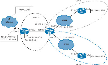
Figure 3-32 Topology for Stub and Totally Stubby Areas
)
OSPF Stub Areas
Example 3-57 displays the OSPF routes in the routing tables of R2 and R3, including external OSPF routes.
Example 3-57 OSPF Routes in R2’s and R3’s Routing Tables
R2# show ip route ospf
<Output omitted>

      172.16.0.0/16 is variably subnetted, 4 subnets, 3 masks
O IA     172.16.13.0/30 [110/20] via 172.16.12.1, 00:56:16, Ethernet0/0
O IA     172.16.14.0/25 [110/20] via 172.16.12.1, 00:56:16, Ethernet0/0
O IA  192.168.1.0/24 [110/11] via 172.16.12.1, 00:56:16, Ethernet0/0
O IA  192.168.3.0/24 [110/21] via 172.16.12.1, 00:54:50, Ethernet0/0
O IA  192.168.4.0/24 [110/21] via 172.16.12.1, 00:46:00, Ethernet0/0
O E2  198.51.100.0/24 [110/20] via 172.16.12.1, 00:01:47, Ethernet0/0
O E2  203.0.113.0/24 [110/20] via 172.16.12.1, 00:01:47, Ethernet0/0
R3# show ip route ospf
<Output omitted>

      172.16.0.0/16 is variably subnetted, 4 subnets, 3 masks
O IA     172.16.12.0/30 [110/20] via 172.16.13.1, 00:53:58, Ethernet0/0
O IA     172.16.14.0/25 [110/20] via 172.16.13.1, 00:53:58, Ethernet0/0
O IA  192.168.1.0/24 [110/11] via 172.16.13.1, 00:53:58, Ethernet0/0
O IA  192.168.2.0/24 [110/21] via 172.16.13.1, 00:53:58, Ethernet0/0
O IA  192.168.4.0/24 [110/21] via 172.16.13.1, 00:45:10, Ethernet0/0
O E2  198.51.100.0/24 [110/20] via 172.16.13.1, 00:00:57, Ethernet0/0
O E2  203.0.113.0/24 [110/20] via 172.16.13.1, 00:00:57, Ethernet0/0
The two external routes, 198.51.100.0/24 and 203.0.113.0/24, are being redistributed into the OSPF domain by R4, which acts as the ASBR and provides Internet connectivity.
Area 0 is the backbone area. The backbone area is the central entity to which all other areas connect. All other areas connect to this area to exchange and route information. The OSPF backbone includes all the properties of a standard OSPF area.
Area 1 is a standard nonbackbone area, in which the type 5 LSAs are flooded from R1. This default area accepts link updates, route summaries, and external routes.
Area 2 is also a standard nonbackbone area. The type 5 LSAs are exchanged through the backbone area (R4 and R1) and the standard nonbackbone areas.
A critical design aspect arises in environments with thousands of external routes. The multitude of type 5 LSAs and the corresponding external routes consumes substantial resources. It also makes the network more difficult to monitor and manage.
Example 3-58 shows ABR R1’s area 1 configured as a stub area. The stub area offers you a powerful method of reducing the size of the OSPF database and routing tables. This area does not accept information about routes that are external to the AS, such as routes from non-OSPF sources. Stub areas cannot contain ASBRs, except when ABRs are also ASBRs.
Example 3-58 Configuring R1’s Area 1 as a Stub Area
R1(config)# router ospf 1
R1(config-router)# area 1 stub
%OSPF-5-ADJCHG: Process 1, Nbr 2.2.2.2 on Ethernet0/1 from FULL to DOWN, Neighbor
Down: Adjacency forced to reset
Configuring a stub area reduces the size of the LSDB inside the area, resulting in reduced memory requirements for routers in that area. External network LSAs (type 5), such as those that are redistributed from other routing protocols into OSPF, are not permitted to flood into a stub area.
The area stub router configuration mode command is used to define an area as a stub area. Each router in the stub area must be configured with the area stub command. The Hello packets that are exchanged between OSPF routers contain a stub area flag that must match on neighboring routers. Until the area 1 stub command is enabled on R2 in this scenario, the adjacency between R1 and R2 will be down.
Example 3-59 shows R2’s area 1 configured as a stub area. R2 is an internal router or leaf router in R2. Once you configure the area 1 as a stub on R2, the stub area flag in the OSPF Hello packets will start matching between R1 and R2. The routers establish an adjacency and exchange routing information.
Example 3-59 Configuring R2’s Area 1 as a Stub Area
R2(config)# router ospf 1
R2(config-router)# area 1 stub
%OSPF-5-ADJCHG: Process 1, Nbr 1.1.1.1 on Ethernet0/0 from LOADING to FULL, Loading
Done
Example 3-60 examines the OSPF routing table on R2 and verifies its connectivity to the Internet destinations 203.0.113.2 and 192.0.2.1. Why can you reach 203.0.113.2 and not 192.0.2.1, although both IP addresses exist on the upstream Internet router? _______________________________________________________________________________________
Example 3-60 Verifying R2’s Connectivity to the Internet
R2# show ip route ospf
<Output omitted>

O*IA  0.0.0.0/0 [110/11] via 172.16.12.1, 00:19:27, Ethernet0/0

      172.16.0.0/16 is variably subnetted, 4 subnets, 3 masks
O IA     172.16.13.0/30 [110/20] via 172.16.12.1, 00:19:27, Ethernet0/0
O IA     172.16.14.0/25 [110/20] via 172.16.12.1, 00:19:27, Ethernet0/0
O IA  192.168.1.0/24 [110/11] via 172.16.12.1, 00:19:27, Ethernet0/0
O IA  192.168.3.0/24 [110/21] via 172.16.12.1, 00:19:27, Ethernet0/0
O IA  192.168.4.0/24 [110/21] via 172.16.12.1, 00:19:27, Ethernet0/0

R2# ping 192.0.2.1
Type escape sequence to abort.
Sending 5, 100-byte ICMP Echos to 192.0.2.1, timeout is 2 seconds:
U.U.U
Success rate is 0 percent (0/5)

R2# ping 203.0.113.2
Type escape sequence to abort.
Sending 5, 100-byte ICMP Echos to 203.0.113.1, timeout is 2 seconds:
!!!!!
Success rate is 100 percent (5/5), round-trip min/avg/max = 1/1/1 ms
Routing from a stub area to the outside is based on a default route (0.0.0.0). If a packet is addressed to a network that is not in the routing table of an internal router, the router automatically forwards the packet to the ABR (R1), which sends a 0.0.0.0 LSA. Forwarding the packet to the ABR allows routers within the stub to reduce the size of their routing tables, because a single default route replaces many external routes.
The routes that appear in the routing table of R2 include the default route and interarea routes, all designated with an IA in the routing table.
You can reach 203.0.113.2 because the 203.0.113.0/24 is being flooded as a type 5 LSA into the backbone area. The first leg of reachability is provided by the default route injected into the stub area by the ABR. The second leg, through the backbone area, is ensured by the existing external route.
You cannot reach 192.0.2.1 because its network is not advertised into the OSPF domain as an external route. Despite the default route out of the stub area to the ABR, the ABR drops traffic to that destination because it does not have a path to the destination. This problem could be solved by advertising a default external route from the ASBR (R4) into the OSPF domain.
In Example 3-61, the ASBR (R4) is confirmed to have a default static route configured. The default route is then advertised into the OSPF domain.
Example 3-61 Propagating a Default Route Using OSPF on R4
R4# show ip route static
<Output omitted>
Gateway of last resort is 198.51.100.2 to network 0.0.0.0
S*    0.0.0.0/0 [1/0] via 198.51.100.2
R4(config)# router ospf 1
R4(config-router)# default-information originate
To be able to perform routing from an OSPF autonomous system toward external networks or toward the Internet, you must either know all the destination networks or create a default route. The most scalable and optimized way is through the use of a default route.
To generate a default external route into an OSPF routing domain, use the default-information originate router configuration command, as shown in Example 3-61. This command will generate a type 5 LSA for 0.0.0.0/0 when the advertising router already has a default route.
The ABR (R1), shown in Example 3-62, examines the injected default route in the OSPF routing table and database. Connectivity to the external destination 192.0.2.1 is verified with the show ip ospf database command.
Example 3-62 Verifying R1’s Default Route
R1# show ip route ospf <Output omitted> Gateway of last resort is 172.16.14.2 to network 0.0.0.0O*E2 0.0.0.0/0 [110/1] via 172.16.14.2, 00:00:15, Ethernet0/0O 192.168.2.0/24 [110/11] via 172.16.12.2, 19:08:02, Ethernet0/1 O 192.168.3.0/24 [110/11] via 172.16.13.2, 19:46:45, Ethernet0/2 O 192.168.4.0/24 [110/11] via 172.16.14.2, 19:46:45, Ethernet0/0 O E2 198.51.100.0/24 [110/20] via 172.16.14.2, 19:46:45, Ethernet0/0 O E2 203.0.113.0/24 [110/20] via 172.16.14.2, 19:46:45, Ethernet0/0 R1# show ip ospf database <Output omitted> Type-5 AS External Link States Link ID ADV Router Age Seq# Checksum Tag0.0.0.0 4.4.4.4 121 0x80000001 0x00C2DF 1198.51.100.0 4.4.4.4 1131 0x80000027 0x0054B7 0 203.0.113.0 4.4.4.4 1131 0x80000027 0x00E943 0 R1# ping 192.0.2.1 Type escape sequence to abort. Sending 5, 100-byte ICMP Echos to 192.0.2.1, timeout is 2 seconds: !!!!! Success rate is 100 percent (5/5), round-trip min/avg/max = 1/1/1 ms
On the ABR, you can see the default route, injected into the backbone area as a type 5 LSA. It appears in the routing table with the symbols O (OSPF), * (default route), E2 (external type 2). You can also see the appropriate LSA 5 in the OSPF database.
Notice the external IP address 192.0.2.1 because the default route directs the traffic via the ASBR. The ASBR has a default static toward the upstream router.
In Example 3-63, connectivity from R2 in the stub area is verified to the external destination 192.0.2.1.
Example 3-63 Verifying R2’s Connectivity to an External Destination
R2# ping 192.0.2.1
Type escape sequence to abort.
Sending 5, 100-byte ICMP Echos to 192.0.2.1, timeout is 2 seconds:
!!!!!
Success rate is 100 percent (5/5), round-trip min/avg/max = 1/1/1 ms
Having flooded the default route as a type 5 LSA into the backbone area, you can now verify that R2 can reach the external IP address 192.0.2.1. The traffic to that destination first follows the default route injected into the stub area by the ABR, and then the default route injected into the backbone by the ASBR.
OSPF Totally Stubby Areas
Next, the ABR’s (R1’s) area 2 is configured as a totally stubby area, shown in Example 3-64.
Example 3-64 Configuring Area 2 as a Totally Stubby Area on the ABR
R1(config)# router ospf 1 R1(config-router)# area 2 stub no-summary%OSPF-5-ADJCHG: Process 1, Nbr 3.3.3.3 on Ethernet0/2 from FULL toDOWN, Neighbor Down: Adjacency forced to reset
The totally stubby area is a Cisco proprietary enhancement that further reduces the number of routes in the routing table. A totally stubby area is a stub area that blocks external type 5 LSAs and summary type 3 and type 4 LSAs (interarea routes) from entering the area. Because it blocks these routes, a totally stubby area recognizes only intra-area routes and the default route of 0.0.0.0. ABRs inject the default summary link 0.0.0.0 into the totally stubby area. Each router picks the closest ABR as a gateway to everything outside the area.
Totally stubby areas minimize routing information further than stub areas and increase the stability and scalability of OSPF internetworks. Using totally stubby areas is typically a better solution than using stub areas, as long as the ABR is a Cisco router.
To configure an area as totally stubby, you must configure all the routers inside the area as stub routers. Use the area stub command with the no-summary keyword on the ABR to configure it as totally stubby. In this example, configuring the total stub on the ABR (R1) breaks the adjacency within area 2 until R3 is configured as a member of a stub area. The adjacency fails because the stub flag in the Hello packets does not match between R1 and R3.
Example 3-65 shows the configuration of an internal router or leaf router (R3) as a stub router in a totally stubby area.
Example 3-65 OSPF Routes in R1’s Routing Table
R3(config)# router ospf 1
R3(config-router)# area 2 stub
%OSPF-5-ADJCHG: Process 1, Nbr 1.1.1.1 on Ethernet0/0 from LOADING to FULL, Loading Done
Once R3 in area 1 is configured as a stub, the stub area flag in the OSPF Hello packets will start matching between R1 and R3. The routers establish an adjacency and exchange routing information. R3 may or may not be configured with the no-summary keyword. The no-summary keyword has no effect when the router is not an ABR and thus does not advertise any interarea summaries.
Example 3-66 verifies R3’s routing table and LSDB information in the totally stubby area.
Example 3-66 OSPF Routes in R1’s Routing Table
R3# show ip route ospf
<Output omitted>
Gateway of last resort is 172.16.13.1 to network 0.0.0.0
O*IA  0.0.0.0/0 [110/11] via 172.16.13.1, 00:18:08, Ethernet0/0
R3# show ip ospf data
<Output omitted>

                Summary Net Link States (Area 2)

Link ID         ADV Router      Age         Seq#       Checksum
0.0.0.0         1.1.1.1         1285        0x80000001 0x0093A6
R3# ping 192.0.2.1
Type escape sequence to abort.
Sending 5, 100-byte ICMP Echos to 192.0.2.1, timeout is 2 seconds:
!!!!!
Success rate is 100 percent (5/5), round-trip min/avg/max = 1/1/1 ms
The leaf router (R3) in the totally stubby area has the smallest possible routing table. Only the intra-area routes are maintained. Interarea and external routes are not visible in the routing tables for each stub area, but are accessible via the intra-area default routes for that stub area. The ABR (R1) blocks interarea and external LSAs and inserts the default route instead.
Despite the minimal routing information about external reachability the leaf router can ping the outside address 192.0.2.1. The traffic to that destination first follows the default route injected into the totally stubby area by the ABR, and then the default route injected into the backbone by the ASBR (R4).
Cost of the Default Route in a Stub Area
By default, the ABR of a stub area will advertise a default route with a cost of 1. You can change the cost of the default route by using the area default-cost command. The default-cost option provides the metric for the summary default route that is generated by the ABR into the stub area.
To specify a cost for the default summary route sent into a stub or not so stubby area (NSSA), use the following command in router configuration mode:
area area-id default-cost cost
To remove the assigned default route cost, use the no form of this command. Table 3-6 shows the parameters available for this command.
Table 3-6 Parameters for the area default-cost Command
|
Parameter |
Description |
|
area-id |
Identifier for the stub or NSSA. The identifier can be specified as either a decimal value or as an IP address. |
|
cost |
Cost for the default summary route used for a stub or NSSA. The acceptable value is a 24-bit number. |
The area default-cost command is used only on an ABR attached to a stub or not-so-stubby area (NSSA). Use the default-cost option only on an ABR attached to the stub area. The default-cost option provides the metric for the summary default route generated by the ABR into the stub area.
The option of tuning the cost of the default route in the stub area is useful in stub areas with redundant exit points to the backbone area, as shown in Figure 3-33. The primary exit point can be configured using a lower cost. The secondary exit point would advertise a higher cost and thus attract external traffic only when the primary ABR fails. This distribution pattern applies only to external traffic. The traffic to interarea networks will follow the shortest path.
)
Figure 3-33 Cost of the Default Route in a Stub Area
The default-information originate Command
To generate a default external route into an OSPF routing domain, use the following command in router configuration mode:
default-information originate [always] [metric metric-value] [metric-type type-
value] [route-map map-name]
To disable this feature, use the no form of this command. Table 3-7 shows the parameters available for this command.
Table 3-7 Parameters for the default-information originate Command
|
Parameter |
Description |
|
always |
Identifier of the area about which routes are to be summarized. It can be specified as either a decimal value or as an IP address. |
|
metric metric-value |
(Optional) Metric used for generating the default route. If you omit a value and do not specify a value using the default-metric router configuration command, the default metric value is 1. The value used is specific to the protocol. |
|
metric-typetype-value |
(Optional) External link type associated with the default route advertised into the OSPF routing domain. It can be one of the following values:
The default is type 2 external route. |
|
route-map map-name |
(Optional) Routing process will generate the default route if the route map is satisfied. |
There are two ways to advertise a default route into a standard area. You can advertise 0.0.0.0/0 into the OSPF domain when the advertising router already has a default route. Use the default-information originate command to allow the ASBR to originate a type 5 default route inside the OSPF autonomous system. The default route must be in the routing table otherwise it will not be propagated by OSPF.
You can use different keywords in the configuration command to configure dependency on IP routing table entries. To advertise 0.0.0.0/0 regardless of whether the advertising router already has a default route, add the keyword always to the default-information originate command. The default route will be propagated by OSPF whether or not there is a default route.
Whenever you use the redistribute or the default-information command to redistribute routes into an OSPF routing domain, the router automatically becomes an ASBR. You can also use a route map to define dependency on any condition inside the route map. The metric and metric-type options allow you to specify the OSPF cost and metric type of the injected external route.
Other Stubby Area Types
The NSSA is a nonproprietary extension of the existing stub area feature that allows the injection of external routes in a limited fashion into the stub area.
Redistribution into an NSSA creates a special type of LSA known as a type 7 LSA, which can exist only in an NSSA. An NSSA ASBR (router ASBR1 in the Figure 3-34) generates this LSA, and an NSSA ABR translates it into a type 5 LSA, which gets propagated into the OSPF domain. Type 7 LSAs have a propagate (P) bit in the LSA header to prevent propagation loops between the NSSA and the backbone area. The NSSA retains the majority of other stub area features. An important difference is the default behavior regarding the default route. ABR must be configured with additional commands before it starts announcing it into the NSSA area.
)
Figure 3-34 NSSA Area
The type 7 LSA is described in the routing table as an O N2 or O N1 (N means NSSA). N1 means that the metric is calculated like external type 1 (E1); N2 means that the metric is calculated like external type 2 (E2). The default is O N2.
The totally NSSA feature is an extension to the NSSA feature like the totally stubby feature is an extension to the stub area feature. It is a Cisco proprietary feature that blocks type 3, 4, and 5 LSAs. A single default route replaces both inbound-external (type 5) LSAs and summary (type 3 and 4) LSAs in the totally NSSA area. The ABRs for the totally NSSA area must be configured to prevent the flooding of summary routes for other areas into the NSSA area. Only ABRs control the propagation of type 3 LSAs from the backbone. If an ABR is configured on any other routers in the area, it will have no effect at all.
To configure an area as an NSSA, you must configure all routers inside the area for NSSA functionality. The area nssa router configuration mode command is used to define each router in the NSSA area as not-so-stubby. Totally NSSA functionality requires one more step; you must configure each ABR for totally NSSA functionality. The area nssa command with the no-summary keyword is used to define the ABR as totally not-so-stubby.